https://www.drduino.com/blogs/news.atomDrDuino - News2023-11-10T00:00:01-05:00DrDuinohttps://www.drduino.com/blogs/news/dr-duinos-escape-from-oonie-island-adventure-in-electronics2023-11-10T00:00:01-05:002023-11-10T00:00:01-05:00Dr.Duino's Escape From Oonie Island Adventure In ElectronicsGuido BonelliMore]]>
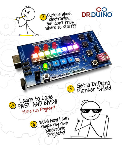
Are you looking to Get Started With Electronics & Coding but just don't know where to even start?
Well then , read on, because this is for you as we just released a brand new kit designed specifically for the beginner.
No Experience Required, No Soldering Or Special Tools Needed!
Welcome to Dr.Duino's Escape From Oonie Island™ an Adventure in electronics and coding!
On your way to taking a much needed vacation, your plane crash lands on a mysterious deserted island.
You appear to be the only survivor, and have to figure out how to not just escape from Oonie Island, but survive and thrive while doing it.
With only your computer and Electronics Survival Kit (ESK) on hand, you'll need to build different electronic gadgets to help you get out of this mess.
With it, you'll use it to help you protect yourself from a blood thirsty island beast, find water & send a message for help, all while learning how to code and build incredible circuits from scratch.
]]>
https://www.drduino.com/blogs/news/dr-duino-inventor-edition-reviewed-by-qst-magazine2023-11-08T11:51:57-05:002023-11-08T11:52:26-05:00Dr.Duino Inventor Edition Reviewed By QST MagazineGuido BonelliMore]]>
Check out the Product Review for the Dr.Duino Inventor Edition, reviewed by none other than Glen Poiel, KW5GP!
]]>
https://www.drduino.com/blogs/news/is-memory-really-that-simple2023-07-11T15:20:35-04:002023-07-11T15:20:35-04:00Is memory really that simple?Guido Bonelli
You've probably seen, when comparing different Arduino boards, a list similar to this:
What is all of that? It's certainly overwhelming for anyone new to the scene.
So let's take it real slow.
Memory.
There's really just two types of memory to consider.
Volatile and Non-Volatile.
No, no, not like whether it's explosive or not, but whether or not it sticks around after losing power.
You see, Non-Volatile memory sticks around after power is removed. It's any type of memory that, well, remembers what it had.
Volatile memory is only good for as long as power is supplied to it. Once that power is gone...WHOOPS...so is what it had, sort of like remembering if you turned off the coffee pot this morning...wait, did I?
Under these two types of memory there are quite a few different names.
We'll start with RAM, and first off you cannot download more RAM despite what that teenager or person on the other line is trying to tell you.
RAM, or Random Access Memory, and of course there are then two types of RAM:
SRAM and DRAM.
Regardless of which we are talking about, static RAM or dynamic RAM, they all have the same basic anatomy.
You see each one of those chips is a memory module. A row of these chips becomes a "page" and a group of pages becomes a "bank".
The cool thing is that within these "banks" are thousands and thousands of tiny momentary switches. These switches can be either on or off, that is, their state is either on or off, a 1 or a 0.
Hopefully, it makes sense how RAM memory is Volatile. If there's no power to "maintain" the switch as it is in its current state then it defaults to being off, thus erasing whatever was stored there.
In an Arduino, SRAM, or static RAM, is where three main data interactions occur. I don't want to dive too far into them because that's for another post, but we have:
Static data - all of the global and static variables that you create get copied to here when the program first starts, think about your Setup() routine and all of the declarations before it.
The Heap - I know a funny name, but it's for holding all of the dynamically changing values and allocated data
The Stack - this holds all of the local variables, it keeps a record of any interrupts and function calls.
Normally, whenever you have memory problems it's because the heap and stack "collide", or data from one gets written over the other. Again, I'll save those details for another post because it can get pretty tricky.
Now let's move on to the other type, non-volatile, or persistent memory - memory that stays even after losing power.
In the case of the Arduino, this type of memory is called flash, or PROGMEM, and it's essentially your program memory. This is where your actual compiled program gets stored and the only way to change it is by re-uploading new compiled code to your board.
Another term for this type of memory is ROM, or read-only memory.
I think that's a bit of a misnomer because whenever you upload to the board you are actually writing to it so it's technically not read-only.
Perhaps than, a better name would be read-only (under most situations) memory, because after the initial write your programs aren't going to, and shouldn't, be changing it.
Flash memory is really cool because their switches don't need to have external power to hold them in one state or the other. The science is actually quite in depth and beyond the scope for a blog post, but just know that once you've set the "switch" it stays in that state until you decide to change it.
Lastly, we come to EEPROM, or electrically erasable programmable read only memory.
Whew! That's a mouthful.
This memory is really slow and it can only be read byte to byte, but it's super useful because you can use the Arduino to make changes to it while your program is running and the data that's stored will persist through a power cycle!
How could that be useful? Well, what if you need to know the last state or function that your program ran right before the power went out? Or what if you need it to pick up where it left off? EEPROM is great for that!
So how do you know how much you should have?
Well, you must consider what you are going to be doing. If you plan on chaining together tons of addressable LEDs and using displays, those items are memory gobblers and will quickly eat up tons of SRAM.
If you have tons of functions and hundreds of different variables then you'll want to make sure you have the largest Flash available to store the program you are writing.
All of this type of memory is used inside of typical Microcontrollers, you know... the ones which are inside of our beloved Arduino and ESP32 boards.
Thankfully, you don't have to worry to much about them, as when you write your code, its all handled for you (depending on what you are doing).
For example, lets say you wan to build your own RGB controller, meaning you can control the color or a Red led, a Green LED and a Blue LED.
Now lets say you want to permanently store those colors that you dial in from an external source, like say a potentiometer.
Well for that you would use EEPROM, dial in what ever value you want from your potentiometers and then simply push them into EEPROM.
Even after power is cycled, you could retrieve those values, and immediately turn on your RGB led to make one of over 16 million different color combinations.
Cool right?
Well, if you want to build that very project, I invite you to check out the Dr.Duino Explorer and Pioneer Editions as that just one of the awesome projects which you'll get to build.
Click the links below to check out both platforms now!
If you're new to Arduino and electronics, then theDr.Duino Pioneer versionis the best choice. Click the photo below to learn more.
Which one will you choose, click here to learn more about the Exploreror here to learn about the Pioneer!
]]>
https://www.drduino.com/blogs/news/how-to-hack-some-hardware2023-03-30T14:15:02-04:002023-03-30T14:17:22-04:00How to hack some hardwareGuido Bonelli
So you've hacked apart some hardware, now what?
Last week you had to get the AVR dude back in line. He just wasn't letting you upload to your Arduino.
Now that he's doing his job properly again, today when you woke up, you woke up with DIY Fever. You decided to hack apart some old tech hoping to hook it up to an Arduino. You're looking down at your shop bench with parts all over and then it hits you. Now what?
Well, now that you've hacked apart some hardware you're looking to get it working with an Arduino.
Problem is, you don't know where to start, and that's okay!
Blocking your path forward is the tough question of how do you make the hardware and the software work together.
You might have a motor, such as a servo or a stepper, a sensor of some kind, or some other interesting part sitting in front you. Regardless of what you have though, the very first thing to do is find a data sheet for it!
Most, but not all, of the time, the hardware that you have will have a part number etched into it or on a sticker.
Looking at the part that I yanked out of a cash register it can be a bit overwhelming. It's got wires, screws, and other stuff hanging off of it, but looking closer and turning it over we find a sticker with some really good information!
See that sticker there. We struck gold!
Not only does it have the serial number (S/N), it also tells us the model number, YAY, and the fact that it operates with a 5-9 VDC power supply, which is always a good thing to double check!
Remember, not every part you yank is going to have all of these juicy tidbits, but you have got to find a model number at the very least.
With that we head right over to our favorite search engine and type the model number in:
So it appears that this part is a thermal printer. What we are looking for now is a datasheet or product manual to go with it.
It just so happens that the first result in the list is the datasheet for this specific model.
That won't always be the case and you might have to dig through a few results until you find the right one.
A good datasheet will have a section for the "general specifications" like I've shown here:
If you haven't already, or are unsure, now is the time to immediately double check what the power requirements are for your device.
After all, if the device requires a voltage that is far outside the typical Arduino voltage of 3.3V or 5V, then it's probably not going to work.
Good news, is this data sheet confirms that printer operates between 5V and 9V.
Now we look into the interface, which is how the device communicates.
With this datasheet we see that it uses RS232/TTL, which is serial communication.
Score!
We can use the Arduino's Rx and Tx to communicate with the device.
Now, you've confirmed it'll work at the proper voltage and you've checked to see that it will in fact communicate with your Arduino, what's next?
Well, most of the datasheets will also contain the serial data instructions. Here's an example:
This one is utilized to get the status of the paper sensor, i.e. is the printer out of paper?
Now I know, this is a bit crazy for a beginner, so your best bet is to search for a premade library like I've done in this example. Notice how I typed in the model number followed by "Arduino".
You can easily put in the model number and ESP32, or model number and Arduino nano, or whatever other flavor of Arduino you have, what you need to find is something with the words, "code" or "library" in the search results.
You'll find a plethora of examples and different libraries to tryout, but after the hard part that I outlined above, the most important thing is that you haven't wasted time trying to get a piece of hardware communicating with the Arduino that just doesn't have the ability or worse operates at an improper voltage burning it out and turning it into a paper weight. *Always make sure that you don't try to power a device from the Arduino, always power the device separately so you don't burn out the chip*.
Those are definitely frustrating times and hopefully you've now learned how to avoid them by finding the right information for the device you're hacking apart.
Are you ready to tryout some DIY hacking?
Then I'd love to invite you to check out our entire line of Arduino Uno and Nano based shields.
Your crisp new Arduino board just came in the mail.
It feels just like when you peel the protective sheet off of your new cell phone.
If there was a "new car smell" it would be power overwhelming!
The excitement is electric as you plug it in to your computer and go to upload the sketch and then....and then....nothing.
Your excitement gets the smack down of the century with an
Okay, this dude is totally uncool, right!?
Well, first off, avrdude is the AVR downloader uploader built in to the Arduino IDE and his job is simple.
He helps take the compiled code and embed it into the chip of your specific Arduino board.
The "stk500_recv()" error is a generic - sort of - catch all error for when there is trouble communicating with your board.
And that's the rub bub. It's a "catch-all" so there is no simple ah-ha do this and it's fixed.
This error will pop up for any number of reasons.
But don't you fret!
I'm here for you and today I'm going to go through my list of potential fixes!
I'll start by doing the simple stuff first.
Are you ready?
Step 1 | Have you turned it off and back on again?
No really.
Many of the communication errors happen simply because the transmitter and receiver are no longer "lock step" and when one should be transmitting it's listening instead.
So, simply put, unplug your board from the computer, wait about 10 seconds, and then plug it back in.
Now try again!
Did that fix it!? Great! My job's done, that'll be $10,000.
Just kidding.
But seriously, never underestimate the power of a power cycle!
See what I did there?
Oomph tough crowd tonight.
Okay, so let's say that didn't work.
Step 2 | Hit the Reset button
If your Arduino board has a reset button, go ahead and tap it.
This soft cycle can also help get it back in sync with the IDE.
And speaking of the IDE, let's try closing it down and the reopening it and if that still didn't work...
Step 3 | You have the right board selected right?
Many times you'll be bouncing back and forth between different flavors of Arduino architecture, from the Nano to the ESP32 back to the Uno and then to the Mega.
All of these boards have different chipsets on them and all of them have different communication protocols.
Think of it like dialing AOL and setting the correct baud rate...okay I just dated myself...
How about we think of it like Mandarin and Cantonese.
Although they are both dialects in the Chinese language, they are not mutually intelligible, that is, knowing one does not mean you can speak the other or be understood by the other.
The same thing happens with Arduino boards.
Communicating requires that you have the correct dialect selected.
So let's look at what our IDE is expecting by clicking the Tools menu.
These three parts are very important.
They tell the AVR dude how to "talk" with the board. Let's look at each one:
Number 1| Board.
Here I have the Arduino Nano selected, which is the standard board for Dr. Duino's Explorer kit.
Make sure you have the correct board selected.
Number 2| Processor.
Here it's set to the ATmega328p.
Sometimes this will need to be set to "ATmega328p (old bootloader)" depending on which chipset gets sent to you.
Unfortunately, this is just a trial and error approach, there aren't any external indicators to help you decide.
Just try one and then the other.
Number 3| Port.
The port is the one that definitely gets messed up the most, especially if you've had multiple boards connected to your computer or swapped to a different USB port, as well.
Just try each one until you get it successfully connected.
PRO Move Alert | Try opening the serial monitor when you change the port by clicking Tools and then Serial monitor, or using the shortcut Ctrl + Shift +M on your keyboard.
If you have the correct port selected you'll be greeted with the serial monitor, if not you'll get a "port busy" error like this one after a few seconds:
If after trying all those steps above you still can't banish the AVR dude from your life, then you may have to dive deeper.
Some things to ask yourself:
Do I need specific or different drivers?
Is my USB cable bad?
Are there any extra shields attached?
Perhaps I have a shorted connection between the Tx and Rx pins?
Was I doing something that could have sent stray voltages through the chip and fried it?
Of course, I can't possibly cover ever scenario here, but if you want to learn more and get an expert in your corner that will help you learn the ins-and-outs, I'd love to invite you to check out our entire line of Arduino Uno and Nano based shields.
If you're new to Arduino and electronics, then theDr.Duino Pioneer versionis the best choice. Click the photo below to learn more.
Which one will you choose, click here to learn more about the Exploreror here to learn about the Pioneer!
]]>
https://www.drduino.com/blogs/news/upgrading-your-electronics-arsenal2022-09-12T13:30:38-04:002022-09-12T13:56:09-04:00Upgrading Your Electronics ArsenalGuido BonelliMore]]>
Recently I've been building more and more projects which has caused me to enough solder, wire and shrink tubing to circumnavigate the earth and moon roughly 43 times.
Ok... maybe not that many times, but you get what I mean...
Because of that, I needed to update some tools and equipment which I want to share with you!
I updated 5 major items in my electronics lab... with that... lets look at them one by one!
Upgrade Number 5 | Shrink Tubing...
I don't know about you, but I can never seem to have enough of this stuff on hand. I always end up with the wrong size. So I bought an entire roll which you see here.
This isn't you're ordinary shrink tubing though! It's marine grade which means it not only shrinks down around your wire it also has glue inside!
I don't know about you, but there are times when it feels like I need a separate room just to house all of my soldering iron bits, solder etc.... not to mention it can get messy.
Well, this handy soldering iron storage system fits the bill perfectly.
I've been using a different type of fume extractor for years, but lately, it just isn't cutting it. The problem with the old one I was using, is that you can't get close enough to where your board is.
Well, this one right here, is totally flat in the front as compared to what I was using, so I can literally set it within a femto inch (.0000000000000001") of my board and feel confident that the fumes are getting sucked into the fan rather than my lungs.
It's a little hard to tell from the image here but this thing is tiny, but don't let that discourage you. I've been using this for about a week now, and its super powerful. I really love it.
I was originally look for a complete de-soldering station, but I don't have a ton of room on my bench. Plus, I don't need to un-solder a lot, but when I do... oy... what a pain.
I currently use a traditional solder sucker and separate soldering iron. So long as I can move at the speed of ninja and manage to get a good suction when swapping out my iron for the solder sucker, all is well. BUT!!! Recently, I needed to do a fair amount of de-soldering. Basically, a component I'm working with has a connector on it, that I don't need. So I had to de-solder a bunch of them.
Well... after loosing what little locks of love I have on the top of my head, I decided I needed to get something.
Well, check this out, because I was pleasantly surprised with just how well this works.
What you see here is a one handed solder sucker with built in soldering iron!
To be honest I was a bit reluctant, but I figured I'd give it a shot and holy shamolies does it work great!
I'm actually in process of cleaning out my lab and my older solder suckers will be going along for the ride. This thing is just awesome.
Sometimes you need a bit more than just a traditional PCB holder, you need something that will give you not just an extra pair of hands BUT added light, magnifying glass and much, much more.
Well, this has to be my favorite upgrade. This all in one PCB holder is perfect especially when you need to do surface mount items. Something which I've been doing a lot of recently.
The magnifying glass is positionable along with the extra set of hands which are moveable.
Well, that's it! I hope you found that helpful, I know for me, this was a sorely needed upgrade!
]]>
https://www.drduino.com/blogs/news/multiprocessing-in-a-single-arduino-is-it-possible2021-10-07T11:22:27-04:002022-01-06T15:26:26-05:00Multithreading in a single Arduino, is it possible?Guido Bonelli
This morning I woke up to an email from a customer asking if multi-threading within a single Arduino is possible.
Meaning, can you do multiple things at the same exact time inside a single Arduino.
This is a really interesting question because at face value, one might think that this is possible.
After all, a single sketch could have a ton of functions or “things” it’s doing.
When you run the code, It might even appear that everything is actually happening at once BUT, this is just an illusion
A sleight of hand if you will. Let me explain.
For the purposes of this blog we will be talking about the two most common Arduino’s ever made.
The Arduino Uno (1) and Arduino Nano(2).
(Image credit arduino.cc)
They both use the same chip at its center the Atmega328P (called a microchip or MCU), one is just physically smaller than the other making it ideal for making projects where space is at a premium.
This particular one is an 8 bit up to 20 Mhz MCU have a look at the specs for it.
(Datasheet source microchip.com)
Compared to what’s inside of your computer, these might seem slow, but for most Arduino projects, this is lightning fast.
AND… this is exactly where the sleight of hand comes in.
If you recall, all Arduino sketches are made up of two sections.
The Setup and the loop, where the setup is only run once at startup and the loop is what runs continuously for as long as power is applied.
Have a look at this piece of code below.
After the program completes running whatever is inside of the Setup(), it then enters the loop().
The Loop() in this code has 3 functions inside of it which will run sequentially forever.
So function1() runs first, then function2(), funciton3() and when its complete with funciton3(), it goes back to function1(). So on and so forth, forever!
The thing is, this is all happening at lighting speed and to the human eye, it might appear as though everything is happening all at once.
But the reality is that only one thing is ever happening at any one time!
Now… lets say that you needed to stop whatever the MCU was doing while it’s in the middle of executing something inside of function2().
You could absolutely do that using something called an ISR (interrupt service routine), and this might also give the appearance that more than one thing is happening at once.
But again, that’s just an illusion.
What the MCU is doing is what’s called “Servicing the interrupt” meaning, the code stops executing whatever its currently doing and goes and takes care of whatever code is inside of the ISR.
But at the end of the day, its only ever doing one thing at a time it’s just happening so fast, its imperceptible.
But what if you actually needed to do two things at the same exact time?
Well, for that you would need multiple Arduino's which act independently. Depending on what you are doing you might then have to notify the other one another via,say the serial port.
Or you could change your architecture entirely and use whats called an FPGA as those can do multiple things at once. But that's a completely different story for another time.
For me, I have yet to find a need to use more than one Arduino Uno or Nano in any of my designs.
But, that is ultimately up to what you are doing and how much horse power you need. I find, that I can do just about anything with a single Uno or Nano.
Well.. that's it, I hope that answers your question if an Arduino type MCU can do multiple things at once!
If you are looking to get started with Arduino OR are a seasoned pro and need a reliable and easy to use development platform, I'd like to invite you to come check out our entire line of Arduino Uno and Nano based shields.
If you're new to Arduino and electronics, then the Dr.Duino Pioneer version is the best choice. Click the photo below to learn more.
Which one will you choose, click here to learn more about the Explorer or here to learn about the Pioneer!
]]>
https://www.drduino.com/blogs/news/can-you-sell-a-product-with-an-arduino-board-inside2021-09-29T11:30:57-04:002024-01-25T10:30:26-05:00Can You Sell a Product with an Arduino Board Inside?Guido BonelliMore]]>
Welcome back to another action-packed blog post where I answer your most burning questions about Arduino!
Recently whilst (whilst is my favorite word), chatting with a buddy of mine about the applications of Arduino, he asked if Arduino could be used in real products?
He specifically wanted to know if he could buy an off the shelf Arduino board like an Uno(1) or Nano(2) and sell it as part of his own electronic widget.
Photo Credit (Arduino.cc)
Example time!
Let’s say that you came up with an idea for a stellar electronic gadget, lets call it the Gizmo3000!
The Gizmo3000 needed electronic control so you turned your trusty arsenal of Arduino boards.
My personal favorite the Arduino Nano because its small, and is one of the most popular boards in Arduino line up with lots of code snippets available.
After feverishly working on the Gizmo3000 and getting it to work just right, you have a eureka moment where you realize, “Hey… wait… I think others would really love this. Maybe I can sell it”.
Now this is where the questions come in.
Can I sell a product with an Arduino board inside?
Is an off the shelf Arduino board robust enough to ship with?
Well, lets dig into each one of these questions one by one.
First… Can I sell a product with an Arduino board inside?
The answer? YES!
You can absolutely sell your own widget which is run by an Arduino board inside.
In fact lots of companies start off this way.
While one could argue that it’s cheaper to make your own board and sell it with that inside instead, I say, skip that part in the beginning.
Why?
For a few reasons.
Cost | Unless you order thousands of your own custom PCB’s with your own design, I can guarantee it will not be cheaper.
Design time |This is a big one, depending on the complexity of your custom board, moving from your Arduino prototyped version of the Gizmo3000 to a full blown custom PCB can take weeks to months to develop. If you want to hit the market with a new electronic product, do it the fastest way possible which is with an off the shelf board.
Is an off the shelf Arduino board robust enough to ship with?
The answer? YES!
There is some miss leading information out there that an off the shelf Arduino board wont handle the rigors of being deployed to the field. This is false (with some caveats).
Chances are your Gizmo3000 doesn’t have the need to meet the rigors of military or space requirements.
If that’s the case an off the shelf board will work perfectly. In fact, do you remember a little known company called Makerbot?
You know, the juggernaut that opened the worlds eyes to 3D printing in the early 2000’s?
Well… they used Arduino compatible board inside and shipped with it!
They shipped thousands of units with it too!
If it’s good enough for a company like Makerbot, its likely good enough for the Gizmo3000.
Pretty neat right?
Well, that’s it. I hope that answers the question of Can I use an Arduino board in my own electronic gadget!
If you're interested in getting started with electronics and coding, then I'd love to invite you to check out our beginner friendly kit!
It's called Dr.Duino's Escape From Oonie Island.
Think Escape room meets, electronics and coding.
It's an story driven adventure in circuits and coding which will teach you step-by-step how to get started with electronics.
By the end of your adventure, you'll have AN EXCELLENT understanding as to how to start building your own electronic gadgets.
Want to learn more? Click the image or link below!
]]>
https://www.drduino.com/blogs/news/reactive-lighting-technology2021-07-07T15:40:35-04:002021-10-14T12:35:44-04:00Dr.Duino's Reactive Lighting Engine for RC VehiclesGuido BonelliMore]]>
Many, many moons ago I used to race my RC car every weekend. I loved everything about it, but then... you know... adult hood.
Well, over the summer I decided to reignite my inner child hood passion for RC car racing and started the hunt to buy something beefy.
Something which has the speed of a cheetah, turning grace of a ballerina, and could take and dish out a beating like randy macho man savage!
After consulting with the great oracle (google) it began to whisper back to me
GET A Slash from traxxas, it said to me, it said...
After doing what us engineers do, (research until your eyes bleed), I traded my credit card digits for the sweet ride you see below!
This thing is no joke, when I tell you it's fast... I'm not kidding this thing has a max cruising speed of around 30 MPH!
That's a three, with a zero miles to said hour after it. While that may not seem fast as compared, to say, a space-x rocket, it is lighting quick on the ground.
When this little bugger is on flat pavement it chews through it like that giant worm thing from the movie tremors.
(Ridiculous side note* - Post writing of this blog, I realized those worms in the movie are called graboids... just thought you might like to know.)
BUT Alas It was missing something...
As I was playing with it, my inner enginerd began to rev its engine way into the red (see what I did there? One... One bad joke ah, ah, ah...)
Any who, I began to wonder what it would look like if I could light up not only the under carriage, but the entire car itself!
But the truck body I had on mine isn't transparent so that wouldn't do.
Luckily, traxxas does sell both a totally clear body and one with some parts blacked out.
I liked the latter as it would help diffuse the copious amounts of lighting I was going to strap to this thing.
However, strapping lights to this, just didn't seem like enough, I mean... come on... this is a huge opportunity to do something epic.
I realized I must do something with those lights which would do more than simply light up my ride.
What if I could tie the motion of the vehicle AND correlate it to various lighting patterns?
GASP RIGHT??
In order to do this, I knew I'd need an accelerometer/gyro. I love the MPU-6050 IMU, they are super simple to use and scarily accurate.
This module measures not only acceleration in XYZ directions but also outputs gyroscope data in XYZ.
This is where it gets its 6 Axis IMU from by the way, 3 from acceleration, and 3 from the gyro.
But the problem I had with using this module was I couldn't quite wrap my brain around which axis did I need to actually measure.
As the truck is zipping and bumping along, would it be clear which axis was actually reacting, and would I be able to translate that into a repeatable lighting sequence?
With that, I knew I was going to need to build a test rig so that I could test out the various directions in a reliable fashion.
I was going to need 2 things in order to accomplish my mission.
1) A mechanical contraption of sorts to give me reliable and repeatable data.
2) An electronics platform which would allow me collect and react to the data.
Hand Me My Drill Please
What you see here is my trusty drill mounted to the shell of my see through slash body. This would allow me to spin the body so that I could monitor the data being spewn out at a few 10's of RPM's.
More on this in a bit.
Next I needed to figure out how I would actually collect the data so I could develop an algorithm for it.
Allow me to introduce what I now call my Reactive Lighting Engine! This would be the basis of my electronic platform!
Reactive Lighting Engine™
One immediate issue I hit was where would I all of the electronics needed in the vehicle itself?
Inside the chassis itself wouldn't work, just too much stuff there. I realized that inside the plastic body itself is plenty of room for 6 to 7 metric tons of electronics and lights.
Since I needed to pack tons of electronics into my RC truck, the Pioneer was the natural choice.
It runs on an Arduino Uno, its compact, has a few buttons which would be critical to helping me debug the axis issues I had (more on that soon), the MPU6050 and tons of LED sticks like the one you see on the Pioneer below.
Spewing Data
In order to make the most of the data, I had 2 ways in which to acquire it. The first would be with using the memory on the Arduino Uno itself.
I could do a bunch of test runs and store the data from the MPU-6050 to the internal EEPROM storage and then read it out on my PC.
But there were 2 problems with that. First, I didn't' know how much data I was going to need and I could potentially run out of room very fast.
Secondly, it was just too cumbersome. I wanted, nay, needed to see the data in real time.
So the only other way to make sense out of the data was to fling it out from a BLE module (bluetooth low energy).
As I drove the car around or as is spun around on my ryobi drill head, I would be able to collect the data wirelessly.
Break Out The Glue GUN!
Given the fact that I would inadvertently be performing barrel rolls through the air, and bashing into things at high speed, I needed to make sure the Pioneer would stay put.
So I whipped out my favorite tool next to my soldering iron, my glue gun. I began applying heavy beads of hot glue to the Arduino Uno (under the Pioneer) and the LED sticks.
MPU-6050 Data
As I eagerly started testing, the amount of data coming from the RC car was voluminous and I just couldn't make heads or tails of it.
I needed a way to easily control and monitor just 1 axis at a time. Using the Pioneer's built in push buttons and some fancy coding, I was able to send out only 1 axis worth of data at a time.
So for example, I would default to spewing out X data at power up, then accelerate the RC vehicle at light speed in just one direction. First forward, then reverse, left and right.
At the same time, someone would be monitoring the data from the BLE module on board via an app.
If we saw a rapid change in the acceleration data, we knew we had the right axis and more importantly were able to characterize what "Forward" looked like in the data.
We would then press the button the pioneer, and try another direction (Reverse) so on and so forth until we were clearly able to see changes in the data which were tied to motion.
This all worked great for the X and Y directions but Z that was the difficult part.
Pitch, Roll and Yaw
For the purposes of this project I really only needed to care about two axis, X and Z.
Where X is referred to as Pitch. Think of this like a seesaw, every time it moves up and down, its pitch is changing.
In the RC car, a positive pitch was when the nose of the car lifts up and the back of the car sinks down a bit.
A negative pitch is the opposite.
The other axis is the Yaw, this is spinning about the Z axis, in the RC car example yaw is when the car turns left or right.
Making Sense Of The Data
Above is the data which was collected from the car in motion separated by axis. As you can see the X /Y (Pitch & Roll) data is easily differentiated, but the Z data (Yaw)... yeah... not so much.
This is when I broke out my ryobi test rig I mentioned earlier. This easily allowed me to collect data exclusively in the Z (Yaw) direction which simulated turning right or left.
As soon as I did this the data became very easy to discern and became cyclical just like the X and Y data you saw earlier.
Putting It All Together
Now that all of the pieces came together, it was time to write the code to collect and react to the motion.
I wanted very clear indicators of the 4 directions so I assigned the following color scheme.
Green = accelerating
Red = Braking
Left = Yellow
Right = Blue
The first few attempts at the code didn't quite work right. When I was collecting the data I was very careful about only looking at one axis at a time and throwing out everything else.
Well... as soon as I enabled all of the code to work together, the positive and negative pitch values seemed to be fighting one another.
So even though it was accelerating and turned the shell of the body green, if I hit a bump the RC car would ever so slightly pitch backwards for a moment.
This in turn signaled to the code to turn the red leds on. However, since it was happening so fast, the colors mixed together creating a flashing orangish color.
While cool, its just not what I wanted.
So... what to do?
Setting Some Limits
The easiest way to address this was to set upper and lower limits which would only get triggered if certain motion was clearly detected.
After combing through the data, it was clear that while accelerating the numbers which came back from the MPU6050 were in the low 1000's. Even at max acceleration.
However, if I hit a bump or the car just bounced around a little during acceleration I would see numbers like 4500 or so.
Also, if I was performing a hard brake, the numbers were around 5000+.
So armed with that knowledge, I built a rudimentary filter to only turn on the RED led's when the number was above 5000.
This worked pretty well but I needed just one more tweak.
Moving Fast While Standing Still
For the times when the RC car was just sitting there, I wanted to put on a light show. So if the Arduino Uno noticed that there wasn't motion for 5 seconds, it would enter rainbow mode which looks pretty cool if you ask me!
The picture below is my traxxas slash sitting still for more than 5 seconds, but if you ask me, it looks like its moving really fast!
Well that's it, that my reactive lighting engine using the Dr.Duino Pioneer shield for its electronic heart and brain.
If you're interested in getting started with Electronics using the Dr.Duino kits, nows your chance!
If you're new to Arduino and electronics, then the Dr.Duino Pioneer version is the best choice. Click the photo below to learn more.
Which one will you choose, click here to learn more about the Explorer or here to learn about the Pioneer!
]]>
https://www.drduino.com/blogs/news/so-what-is-arduino-exactly2021-05-19T21:02:21-04:002024-01-24T11:30:46-05:00So What Is Arduino Exactly?Guido BonelliMore]]>
This is in the one of the most common questions I get asked and today I'd like to answer that for you!
Let's dig in...
Arduino is actually the name of the company that really started the entire maker movement in the early 2000's.
It was started by 4 friends in Italy that decided to create an electronics platform which could be used by both engineers and hobbyists without the need for a PHD in rocket science.
The first board they released is called the Arduino UNO, meaning the number one in Italian. That's the board you see here on the left.
Over time, it became apparent that customers wanted a smaller form factor of the same board and so the Arduino Nano was born. That's the board you see above on the right.
Believe it or not, they both are exactly the same! One is just smaller than the other.
But What Is It In Laymen Terms?
Have a look again at the photo above, specifically at where the numbers 1 and 2 are.
That right there, is the reason the electronic world around us exists, not just Arduino.
Let me explain...
Those numbered components are called microcontrollers (sometimes referred to as a micro or MCU).
Think of it like a tiny, brain which you program to make it do whatever you want using a programming language called C.
It can also be programmed in C++ but that's a story for another time.
Inside of these micros are microscopic transistors.
If you're not familiar with what a transistor is, think of it like a switch.
It's the building blocks of every electronic gadget you own!
And manufacturers can fit a mind boggling amount of these into these tiny packages.
When I say mind boggling, I mean numbers ranging from a few hundred, to a few hundred THOUSAND all inside of something no bigger than the size of your pinky nail.
In reality, its much smaller than that, but you get the idea, they can fit a ton in a really small area.
Now... these transistors are arraigned in a very specific way to provide very specific functionality.
They can do everything from lighting simple LED's to controlling sophisticated motors in your drone and everything in between.
Prior to Arduino hitting the scene, if you wanted to get into electronics and start using Microcontrollers, you needed an electrical engineering degree.
And then you needed to swim through miles upon miles of documentation for that particular micro.
Through a lot of trial and error you could eventually get your mirco to do some pretty awesome stuff.
But as you can imagine, development was ssslllloooowwwwww.
I'm talking a sloth could swim across the English channel 12 times before you could get it to light a simple LED.
Thankfully, Arduino came along just in time!
ENTER ARDUINO!
When Arduino hit the scene they wanted to simplify all of this, they wanted a system so easy to use that anyone could make amazing electronic projects in minutes not months!
In order to do this, they had to create a simple to use piece of hardware (Uno and Nano) and made it into the standard form factor you saw earlier.
Next, they simplified the programming language and also the program you use to actually do your programming called the IDE.
Thanks to Arduino, making any electronic idea come to life is really simple.
Well, that's it, that's Arduino in a nutshell!
However, in order to really harness the power of it, you need to attach your Uno or Nano to other hardware.
You need things like switches, LED's buzzers, tri-colored LED's, a super cool display and of course BLE for communicating with other hardware.
But that's just getting you started, what you really need to get into Arduino is a robust, reliable kit that has cool projects and even better support.
If you search for Arduino kit on google, boy oh boy, will you see gatrillions of kits.
But which one do you choose? What's a good kit? Where do you even start?
Well, that's why I created the my own kit which teaches you the fundamentals of coding and circuits in a FUN way without needing a PHD in BioRocketryEngineering (is that a thing??, anywho...)
It's called Dr.Duino's Escape From Oonie Island.
Think Escape room meets, electronics and coding.
It's an story driven adventure in circuits and coding which will teach you step-by-step how to get started with electronics.
By the end of your adventure, you'll have AN EXCELLENT understanding as to how to start building your own electronic gadgets.
Want to learn more? Click the image or link below!
For example, if you’re application needs a screen to display fancy graphics then this is definitely the way to go.
The latest Rpi 4 has the ability to support dual 4K display screens, supports USB 2,3 & C and even has a built in Ethernet jack.
Now here’s where things get interesting, its also has a bunch of general-purpose inputs/outputs (I/O) which you can attach sensors and all sorts of other things to.
If you read my last blog post, this is going to sound familiar because an Arduino has this same set of features. It has a bunch of I/O which you can attach sensors to and make motors spin etc.
But here is a key distinction which might lead you to chose one over the other.
Please queue the second drum roll…
An operating system, yup, an operating system like windows or iOS.
You see Rpi needs an OS in order to do its thing, while Arduino does not.
Now, let’s say your application needs to just read a bunch of sensors and take some action then Arduino is definitely the way to go.
That’s because using an Rpi just for the ability to gain access to all the I/O requires you to tunnel through the OS which is a bit more complicated.
Especially if you’re just getting started.
However, since Arduino doesn’t have an OS, its WAAAAY easier to interface to sensors, motors, LEDs etc.
It's also a lot faster to get up and running, but that's just my opinion.
So, which one’s “better”? I leave that decision to you, if you are looking to get started with electronics & coding using an Arduino compatible kit, I'd like to invite you to check out one of our most popular kits.
If you're interested in getting started with electronics and coding, then I'd love to invite you to check out our beginner friendly kit!
It's called Dr.Duino's Escape From Oonie Island.
Think Escape room meets, electronics and coding.
It's an story driven adventure in circuits and coding which will teach you step-by-step how to get started with electronics.
By the end of your adventure, you'll have AN EXCELLENT understanding as to how to start building your own electronic gadgets.
Want to learn more? Click the image or link below!
]]>
https://www.drduino.com/blogs/news/eejournal-featured-article-how-dr-duino-can-help-get-you-started-with-microcontrollers-and-programming2021-04-29T15:10:56-04:002021-04-29T17:05:29-04:00EEjournal Featured Article-How Dr.Duino Can Help get you Started With Microcontrollers and ProgrammingGuido Bonelli
Check out this fantastic article in EEjournal about getting started with Programming and Microcontrollers. There is an entire section dedicated to the Dr.Duino shields!
]]>
https://www.drduino.com/blogs/news/what-can-you-do-with-arduino2021-04-29T09:25:25-04:002024-01-25T10:15:48-05:00What can you do with Arduino?Guido BonelliMore]]>
I get asked this question a lot, like A LOT, A LOT!
Ready for the answer?
Drum role please...
It's actually easier to answer what you CAN'T do with Arduino!
Yup, its just one of those tools that is just so diverse, it can be used in just about anything.
Think of it like the salt and pepper of electronics, it goes on everything!
But there are things which it is just not well suited for.
Lets lay the framework though, because over time Arduino has released some pretty awesome boards which have some stunning capabilities.
So for this purposes of this blog post, when I say Arduino, I am referring to boards like the Arduino Uno (left photo), Nano (right photo) as these are hands down the most common boards out there.
Photos from Arduino.cc
OK back to what you CAN'T do with Arduino.
The easiest way to figure out if your idea is suited for Arduino or not is to ask yourself just one question.
Does it need to do PC type things?
If it does, then Arduino is NOT going to work in that application.
Let me explain...
I have a buddy who just started getting into mining virtual coins (bitcoin and doge coin).
WARNING... MASSIVE OVER SIMPLIFICATION COMING!
If you're not familiar with what this is, its boils down to trading electricity for money.
Using a PC you would query a website for a very, very, very long and complicated math equation.
Then you run a specialized program on your PC to solve the equation.
Once it does you are left with a small fraction of a virtual coin which is worth some amount of real money.
Think of it like physically digging through a giant pile of dirt looking for small flakes of gold.
You're doing the same thing with your PC and some math instead of a shovel and then sifting through it for gold.
This is a prime example of what you CAN'T do with Arduino.
HOWEVER!!!!!
Arduino can play a critical role in your virtual mining operation. Ready?
HEAT Monitoring!
You see, part of the process of mining for bitcoin is that your PC will get VERY, VERY HOT!
It's just the nature of the beast, your PC needs to work very hard to solve the complex equation.
As its solving the equation, the internal chips get hot, VERY HOT!
Wouldn't it be awesome to take some sort of action once your PC gets too hot?
You'd be able to turn on a few fans, maybe turn on a water cooling system for the PC itself, then notify you via text message, horns, BIG flashing lights?
Well... this is an example of what you CAN do with Arduino!
You see, Arduino type boards are perfect for doing two things (generally speaking).
First, It's Perfect For Environmental Monitoring.
In the example I gave above, this would mean monitoring the PC for its temperature.
To do this you would simply need some sort of temperature sensor which is near your PC.
The Arduino's job would be to sit and sample that temperature sensor forever and ever and ever and... EVER!
Second, Taking Some Action!
This actually breaks down into two separate forms.
Either electrically or PHYSICALLY!
When I say taking electrical action, I'm referring to sending you a text message.
You could do this by adding a simple Wifi module to your Arduino which then is able to speak over the interwebs to notify you via text message that your machine is HOT!
Now... when I say Physically, I'm referring to turning on a fan, water pump, lights and giant buzzer.
You would do this with some external hardware.
Pretty simple right?
Well, that's it, that's how to easily tell what you CAN and CAN'T do with Arduino.
I hope that you have gotten a lot out of this and that you can now easily tell if Arduino is right for you!
If you're interested in getting started with electronics and coding, then I'd love to invite you to check out our beginner friendly kit!
It's called Dr.Duino's Escape From Oonie Island.
Think Escape room meets, electronics and coding.
It's an story driven adventure in circuits and coding which will teach you step-by-step how to get started with electronics.
By the end of your adventure, you'll have AN EXCELLENT understanding as to how to start building your own electronic gadgets.
Want to learn more? Click the image or link below!
]]>
https://www.drduino.com/blogs/news/dr-duino-explorer-reviewed-in-qst-magazine2021-01-12T13:32:27-05:002021-01-12T13:37:45-05:00Dr.Duino Explorer Reviewed IN QST Magazine!Guido BonelliMore]]>
Your Grab & Go Arduino Development Platform is here!
Today I'm super excited to bring to you ANOTHER review by the folks over at the ARRL! This time for our Explorer Edition.
]]>
https://www.drduino.com/blogs/news/explorer-and-pioneer-manuals2020-12-25T14:39:44-05:002020-12-27T09:49:13-05:00Explorer and Pioneer ManualsGuido BonelliMore]]>
Looking for the Dr.Duino Explorer or Pioneer Shield assembly manual?
Immediately after you purchased, you were sent an email titled
🧪Welcome To Dr.Duino's Labs🧪
This email contains login in formation which will gain you access to the assembly manual, code and much more.
Please search your spam folders if you don't see it in your regular email inbox.
Can't find it? No worries. Send us a help ticket, and we will resend you the credentials!
Help desk is found at the bottom right hand corner of your screen. Click it and send us a note.
Did you receive a Dr.Duino as a gift?
If you received the Dr.Duino Explorer or Pioneer as a present, you can request membership too! Simply fill out the information in our survey.
You will need some information from the person who gave you the gift. Simply ask them for the email address they used to purchase it and then click this link below.
]]>
https://www.drduino.com/blogs/news/learn-how-to-solder-in-5-easy-steps2020-12-22T18:06:07-05:002020-12-24T08:42:23-05:00Learn How To Solder In 5 Easy Steps!Guido BonelliMore]]>
I know sometimes soldering can seem intimidating and down right frustrating. So I broke it down into 5 easy to follow steps which will make is so much easier!
]]>
https://www.drduino.com/blogs/news/make-magazine-reviews-dr-duino-explorer2020-11-24T21:02:51-05:002020-11-25T11:34:06-05:00Make Magazine: Reviews Dr.Duino Explorer!Guido BonelliMore]]>
I remember when the maker movement first hit the scene in the early 2000's and was super excited to see a magazine that catered exclusively to us makers.
You know... Make Magazine!!! Well... I'm still a super huge fan but especially this month!
If you haven't received your copy yet, check out page 126 of issue 75 where none other than Makes Executive Editor, Mike Senese reviews the Dr.Duino Explorer!
It made it into the ever popular TOOLBOX section too!
Without further a due.. the Dr.Duino Explorer as seen in
As someone approaches it will begin to howl (or whatever sound you want) , the lights built into the Pioneer will start illuminating and that little ghost you see there will begin to wave back and forth.
Pretty awesome right!
So just set it out next to your candy dish this Halloween and watch the kids get a nice trick and treat at the same time!
Oh and this isn't the only thing you can build with this kit. It actually has up to 14 different things you can build!
]]>
https://www.drduino.com/blogs/news/dr-duino-pioneer-reviewed-in-qst-magazine2020-10-07T10:43:27-04:002020-11-25T11:34:30-05:00Dr.Duino Pioneer Reviewed IN QST Magazine!Guido BonelliMore]]>
Ham radio enthusiasts your Arduino Uno Learning Platform Is HERE!
Today I'm super excited to bring to you a review by the folks over at the ARRL!
Check out the review written by non other than Glen Popiel, a regular in the Ham radio community, creator and all around master ham operator.
It is in this months QST magazine on page 51, and really highlights the power of the Dr.Duino Pioneer for those new to the Arduino landscape.
]]>
https://www.drduino.com/blogs/news/stackoverflow-interview-dr-duino-helps-us-diagnose-what-s-next-for-arduino2020-10-06T10:18:56-04:002020-11-25T11:34:45-05:00Stackoverflow Interview: Dr. Duino helps us diagnose what’s next for ArduinoGuido BonelliMore]]>
Late last week I had the honor of being on the Stackoverflow podcast hosted by Ben Popper, Sara Jo and Paul Ford.
It's always great to speak with fellow techies and discussing my favorite topic, Arduino!
We delve into how the Dr.Duino brand got started, where the name came from and the every popular Gooniebox!
]]>
https://www.drduino.com/blogs/news/dr-duino-explorer-model-rail-road2020-08-05T14:29:00-04:002020-08-05T17:05:36-04:00Dr.Duino Explorer & Model Rail Road Lighting EffectsGuido BonelliMore]]>
Over the past few months, I've been dabbling in the model railroad space. Its been a very happy and nostalgic reminder of my childhood.
But boy have things changed. The level of control you can now incorporate is just insane.
But the issue I found is that in order to light your crossing signals or add some sound or just about anything else, requires these funky stand alone modules which are roughly 4 bajillion dollars.
I can't give away too much info right now, but I am going to be releasing some very cool model rail add-ons in the near future so sign up below if your interested in knowing when that's available.
Simulating Hardware
Before I wired stuff up in my model rail layout itself, I needed to scratch out some concepts I had.
So I could find out what I liked/didn't like, what would work, what wouldn't etc.
One of the things I was really interested in doing was creating realistic lighting effects.
Luckily, the Dr.Duino Explorer, has a built in 16 million color capable LED stick.
Creating Realistic Flames
In the video, you'll notice that I wanted to create a flickering effect which would simulate something being on fire.
So things like a fire pit, or oven or anything else which requires a nice flicking shimmer.
I did this using a one of the 8 on board LEDs by mixing Red and Green together to create a nice orange color.
But here's the clincher, in order to make it look real, I didn't just want to set a static delay between turning on and off.
Using this in conjunction with the color mixing, it created a really nice and more importantly, realistic flame color and effect.
Now all I need to do is bury one of these LED's inside a pile of sticks to simulate a fire burning just like this one.
The Code
Below is the code I used to create the fire lighting effect. Feel Free to use it, you will need to install the adafruit neopixel library for it to work.
I've also posted the code here so you can just copy and paste, just take everything in red below.
/*Dr.Duino Lighting Effects Demo Code * for the model rail fan. * www.DrDuino.com * */#include <Adafruit_NeoPixel.h> Adafruit_NeoPixel strip(8, 6, NEO_GRB + NEO_KHZ800); int ToggleFlashPattern = 1;
//----Modify these values below int RedComponent = 255;// Full Red int GreenComponent = 20; // Just a touch of green. int FlickerRandomDelay = 50;// Change this number to adjust the randomness of the flickering. recommend anything less than 50
void setup() { // put your setup code here, to run once: strip.begin(); // Initialize NeoPixel strip object (REQUIRED) strip.show(); // Initialize all pixels to 'off' }
void loop() {
if(ToggleFlashPattern == 1) { /* Notice that we are passing in the Red and green values. * They are set up in the variables section. * Red is set to 255 and Green set to 20. * This gives a orange kinda color. Mess with these numbers * till you get what you like. 0-255 is valid. * We are also putting in a random number delays betwen turning * on and off. This gives a more reaslistic feel to the simulated * fire. */ strip.setPixelColor(0, strip.Color(RedComponent,GreenComponent,0)); delay(random(FlickerRandomDelay)); } else { strip.setPixelColor(0, strip.Color(0,0,0)); } ToggleFlashPattern = !ToggleFlashPattern; strip.show(); // Show the lights }
That's it!
I hope you found that useful, if you want to know more about when the model railroad edition will be rolling out, just sign up below!
]]>
https://www.drduino.com/blogs/news/df-mp3-player-from-dfrobot2020-07-09T11:39:00-04:002020-07-09T11:40:30-04:00DF MP3 Player From DFRobotGuido BonelliMore]]>
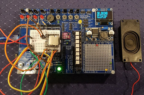
Adding Sound To Your Arduino Projects, FAST!
Recently I started working on a project where I needed to add sound, and ALOT of it too! But with the myriad of options out there it can be really bewildering as to which platform to choose.
Historically, I've always gone to my go to chip set called the CHIPCORDER from a company called Nouvoton.
I really only ever needed to add a sound byte here, a sound byte there. But in this instance, I needed to add a bunch of clips and of varying length so my beloved ISD series of chipcorder just wouldn't do.
I also needed it to be loud without a lot of external components.
Mini MP3 Player
When you do some searching for MP3 players which are Arduino driven, you get back approximately 65412316541326876132165 x 10^2316 options.
Boy... my head nearly exploded. Luckily, a buddy of mine who owns Programming Electronics Academy, just released a massive new course on this exact topic.
So I ran on over and checked out his video course. If you haven't want to learn about programming Arduino or this course in particular, you can signup for his courses here. You won't be disappointed.
It uses a standard SD card which gave me boodles and boodles of storage. A built in amplifier which once connected to a 3 Watt, 8 Ohm speaker is MORE than loud enough for my application.
This was the perfect combination for me, but there is a weird little hiccup I ran into and wanted to share it so that you don't waste a load a time like I just did.
First the build...
Building the Circuit
I needed a few buttons to trigger the various tracks, a potentiometer to vary to volume and a new display to output what track was being played. So I turned to my trusty Dr.Duino Explorer Edition and got it hooked up in about 34 femto seconds.
I tied the buttons on the Dr.Duino Explorer to trigger each sound clip on the SDCard.
So button 1 on the shield would trigger the 0001.mp3 sound, button 2 would trigger 0002.mp3 etc.
Que the image of head popping
But as I began to play around with the sounds, I noticed that button 1 would play sound 2, button 2 would play sound 1, button 3 would play sound 4 and button 4 would play sound 3.
I thought I had messed up the mappings on the switches to the sound clips so checked my code, and then rechecked, and then checked with a side of check checking.
And... it was all correct.
Then I dug into DF robots page and found this little snippet.
NOTE: The order you copy the mp3 into micro SD card will affect the order mp3 played , which means play(1) function will play the first mp3 copied into micro SD card.
So in the end, the number which I assigned to the mp3 files was irrelevant, just the order in which I copied the files down to the sdcard!!!!!
I then copied off the renamed mp3 folder from the SD card. Reformatted the SD card and then re-copied the files back to the SD card.
POOF! It all worked as expected.
What's that old saying? The devil is in the details? Well... that certainly proved true today!
Well.. until next time, I hope you found that useful.
]]>
https://www.drduino.com/blogs/news/customer-project-by-jerry-p-american-flag-waving-machine2020-07-07T14:11:00-04:002020-07-07T16:17:45-04:00Customer Project By Jerry P. American Flag Raising MACHINE!Guido Bonelli
American Flag Raising Machine
Today I’d like to show you a project made by one of my customers Jerry P, who is a retired engineer who worked for NASA, JPL and Raytheon .
He created an awesome Patriotic American Flag raisin, music making machine using the Dr.Duino Pioneer shield.
Instead of using an Arduino Uno, he actually used an STM32F446 development kit writing all the custom code.
Volume UP! You’ll love this.
]]>
https://www.drduino.com/blogs/news/dr-duino-pioneer-explorer-editions-released2020-05-26T08:13:00-04:002020-06-12T09:55:26-04:00Dr.Duino Pioneer & Explorer Editions Released!Guido BonelliMore]]>
NEW Dr.Duino Products Announced!
Two New Shields | An Electronics Eco System
Building and tinkering with electronics will never be the same with Dr. Duino’sTM latest Arduino compatible shields. These are complete, compact learning and prototyping systems which are perfect for anyone interested in electronics.
Pioneer Edition | Learning Platform
Designed with the beginner in mind, the Pioneer Edition helps you easily learn about the awesome world of electronics through hands on projects. Arduino Uno compatible.
Explorer Edition | Prototyping System
Designed with the experienced user in mind, the Explorer Edition helps you build and test your electronic concepts FAST! Jam packed with powerful features; you won't know how you developed without it! Arduino Uno & Nano compatible.
Expansion Pack | Exclusive Dr.Duino Projects
Build awesome projects right out of the box with the expansion pack. Highly detailed and fun to build, you will love making these great projects.
Demo Code | Go beyond blinking an LED
Most Arduino based kits come with demo code which is, well, kinda lame. Not with your new Dr.Duino Pioneer or Explorer shields.
Each kit comes with up to 10 USEFUL and FUN code to play with.
Since I was relying on this data to know how far something was away from me, getting that random 30" when clearly nothing was that close, was a real issue.
So what to do?
Well, I applied what's called a bubble algorithm and added a bit of a twist to it.
A bubble sorting algorithm just sorts your data from low to high or high to low depending on how you write your code.
If you noticed, the example data I gave had 13 data points. This was done on purpose.
If we apply a bubble sort to these numbers from low to high, here is what the data looks like now:
Now, the next step is to isolate the median number which in this case is 150 and is the 7th data point.
Which leaves us with 6 lower data points, and 6 higher data points hence choosing 13 data points!
Now we can get the exact middle of the data sequence which is 150.
28,30,147,147,148,148,150,150,150,150,150,159,159
I could have just left it at that and used that for making decisions, but I wanted a bit more accuracy.
So I ended up averaging the middle 3 data points (in red):
28,30,147,147,148,148,150,150,150,150,150,159,159
With that, we get a nice average value of 149.333", which is pretty stable in terms of data.
Using the Data
Now that I had the data which was pretty stable, I created a color-coded dial that visually indicated to the person approaching you how close they are.
And your current "distance mood" which ranges from A-ok, to BACK UP THE BUS! You're too close!!!
Using the data from the ultrasonic sensor, I then divided up the distance as follows:
Green = More than 13 feet or 150" away = A-Ok
Yellow/Green = Less than 150" but more than 114" = You're Good
Yellow/Orange= Less than 114" but greater than 93"= Ummm....
Orange/Red = Less than 93" but more than 72"= You're a bit too close!
Red = Less than 72 Inches = BACK UP THE BUS!
Once the person does get too close, the final touch was to add a very "New York" response. Watch the video to find out what it is!
The Hardware
While it's true that under the covers I'm using an Arduino Uno, servo, ultrasonic sensor and an ISD-1820......it's also built with the newest addition to the Dr.Duino product line, but I can't talk about it yet.
Here is a nice, crystal clear picture of it though... does that help ? ;)
Sorry, couldn't help myself. But the details will be released in the next few weeks.
So stay tuned.
Well... that's it. I hope you enjoyed this little write up on using the HC-SR04 sensor to make your very own back up the bus detector!
If you liked this and would like a chance to win the hardware to build it, signup for my giveaway below!
It will do much more than just this social distancing example, its a full blown Arduino based, learning eco system.
Sign up for free below!
]]>
https://www.drduino.com/blogs/news/uploading-arduino-code-without-the-arduino-ide2020-02-22T09:20:00-05:002020-02-22T09:20:29-05:00Uploading Arduino Code Without The Arduino IDEGuido BonelliMore]]>
Have you ever needed to share your Arduino code with someone, but didn't need or want to send the source code?
How would you upload the code to your Arduino Uno, nano or other?
Well... Arduino under the covers uses AVRDUDE which is what is actually handling compiling the code and whisking your 1's and 0's to your Arduino.
The cool thing is that you can manually use AVRdude without the Arduino IDE itself.
I found this really great video on how to do it and thought it might be useful for you too!
]]>
https://www.drduino.com/blogs/news/what-the-heck-is-my-arduino-doing2020-01-14T20:06:00-05:002021-06-03T15:55:50-04:00What the heck is my Arduino doing?Guido BonelliMore]]>
Recently I was working on a program where I needed to write a ton of information to the serial monitor.
Well... all of a sudden some super weird things started happening. If statements wouldn't execute sometimes, other times, the program would appear to just stall.
After ripping out what little of my locks of love which I have left (aka hair on my head), I turned on verbose mode in the Arduino compiler.
PS- to turn on verbose mode, aka tell me all the gory details about what the compiler is doing, go to File\Preferences then click on verbose mode.
Well, well, well... what did we see there?
I WAS RUNNING OUT OF MEMORY!
But how could it be, my program really wasn't doing anything aside from a bunch of printf's.
After some digging, I realized that whenever you call Serial.print it's storing that in SRAM of which we have precious little in our beloved Arduino Uno which uses the Atmega 328p chip.
UGH.. what now?
Well after consulting the great google, I realized that there is a workaround.
Instead of using the serial monitor like this
Serial.println("Hi, I used up all of Dr.Duino's memory");
Just change it to
Serial.println(F("Hi, I used up all of Dr.Duino's memory"));
What does that lowly F do? Great question.
It tells the compiler to use your flash memory which you have tons of instead of your RAM.
and TADAAAAA.... my program compiles again and isn't acting all squirrely.
Well.. thought I'd share that nugget of love with you as I only have a few sprigs of hair left and that was driving me nuts.
If you are looking to get started with Arduino OR are a seasoned pro and need a reliable and easy to use development platform, I'd like to invite you to come check out our entire line of Arduino Uno and Nano based shields.


 No, no, not like whether it's explosive or not, but whether or not it sticks around after losing power.
 I think that's a bit of a misnomer because whenever you upload to the board you are actually writing to it so it's technically not read-only.